


DimLux Maxi Controller: setup and connections
Which Maxi Controller, software and cable suit your DimLux fixture? Prepare the connections and check lighting schedules, dimming and sensors for your generation.
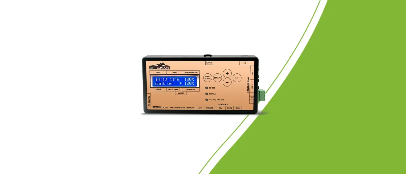
Identify the controller and fixtures first
Record the exact Maxi Controller model, software version and complete fixture names. EVO 1.2 and Datalog versions should not be treated as identical without checking. The equipment combination determines connections and available functions.
List the functions you want. A lighting schedule alone requires a different combination from lighting with temperature control, leaf measurements and additional climate equipment.
Match the controller and fixture generation
Older and newer DimLux systems use different connections. Check the output, communication type and external control mode for your combination. A port name from an older system does not apply automatically to every Xplore or Xtreme.
The older Xplore 730W/730W 9X combination with Maxi Controller requires software 5.0.10 or newer. Check the version before connection and have an older controller updated if necessary. This requirement applies to that particular combination rather than every DimLux generation.
Choose a suitable communication cable
The older Xplore 730W/730W 9X combination with Maxi Controller uses communication cable 2-955. Match the component to the controller and fixture generation. Do not choose a random cable merely because the plug fits.
Similar connectors can serve different functions. Use the specified cable and verify the route from controller to the first fixture and between fixtures. Communication wiring does not replace each fixture’s own power supply.
Check scheduling and dimming step by step
Record controller and fixture models, software version and cable type.
Check the cable route and the external control mode for the combination.
Select the correct fixture type in the controller.
Check the clock, light period and intended output.
Test control and confirm that the fixture responds to a change.
Change one setting at a time and record the result. If a fixture does not respond, do not keep increasing output. Check mode, cable route, software and selected fixture type first.
Add sensors for the function you need
An air temperature sensor supports temperature-based lighting control. A plant temperature camera measures the leaf surface. The described VPD display also requires RH and air temperature readings. Having a controller does not mean every sensor is included.
Check extension hardware when you want to operate a fan, heater or humidifier. A sensor measures a value; switching connected equipment requires a suitable combination.
Record the final setup
Keep model names, software version, cable references and settings together. Photograph the connections after checking operation. This helps with future expansion and advice requests.
When asking for help, include the fixture generation and the function that is not responding. That allows the correct connection diagram to be chosen.